HOW TO FIX AN EPC PROBLEM, - CONTINUED
The final note on the preceding blog installment ended on 'scan for Diagnostic Trouble Codes with a scan tool'. However before we start scanning it is important to note, that Vehicles from year 2000 are fitted with an EPC (Electronic Power Control) system, hence this exposée only applies to cars fitted with a obdii 16 pin female connector, identifiable by its normally purple core, roughly the same purple of the 6-pin mini-DIN connector of a personal computer keyboard. This EPC system / Drive-by-Wire circuit (implying no throttle cable) is also known as the torque circuit. The EPC system controls the EPC light which turns on if and when there is the slightest malfunction in the Drive-by-Wire circuit. Any such fault will more than likely generate a DTC (fault code) in the ECM, which is stored in its non-volatile memory, meaning even if the battery is disconnected afterwards the DTC (fault codes) will persist. However, also note that when the battery is disconnected all driver learnt values particular to your driving style, will be erased. Disconnecting the battery may require resetting the convenience electronics, such as alarm, interior lights and the radio. So, most importantly if you don't have the radio code, practice caution because the radio will permanently lock-up hence it's a good idea to use a jumper battery or perhaps even a battery charger to maintain battery power whilst replacing a battery. Or get the code from your service center.
Whilst any problem in the torque circuit is normally responsible for turning on the EPC light, the EPC light may also turn on for some other non-emission related engine faults. When a combination of emission-related and EPC-related fault is encountered, both the MIL and EPC lights may turn on. This alone give one a good idea of whether or not the engine problem is purely torque related or part of an emission-relate issue.
Most pure torque circuit EPC faults are accompanied by Limp-Home Mode which revolve around the basic settings for the Electronic Throttle Control Valve Adjuster, Idling Control, EPC Adaptation and the Accelerator Pedal Position Senders. Their values are stored in the ECU normally from group 60 - group 62 of the Bosch ME 7 and newer ECUs, however the actual group may vary subject to make, model and engine capacity of the vehicle. For example. Jetta, Polo, Audi TT, etc, EPC adaptation exists at group 060 - group 062, whereas these values may be stored in group 098 for some VW Passat and Audi A4, S4, B5.
Group=060, Adaptation Epc-system
Group=061, Epc-system (1)
Group=062, Epc-system (2)
Looking at the diagram for accelerator pedal senders G79 and G185, pins 50 and 19 are inputs from their respective highside driver 5V supplies with pins 18 and 45 of the ECU microprocessor are their independent internal earth connections. The two variable voltages at pins 51 and 64 are the inverse of on another. Essentially G185 (secondary) is working as a backup to G79 (primary). Inputs at pins 51 and 64 are constantly monitored by the ECU microprocessor could range from sporadic to too high or too low, to intermittent to absolutely not there. The ECU microprocessor with its built-in Watchdog Supervision Safety Logic monitoring performing plausability checks for voltage regulation, Over/Under voltage levels, intermittent voltage levels. If for any reason that the calculations based on its internal algorithms do not correspond to its internally stored and expected values either the watchdog processor or the Main Processing Element enable a secondary shutdown path to all equipment under its control. In a nutshell, limp mode.
Constant movement of the gold plated contacts on the potentiometer slider eventually wears through and becomes intermittent especially if the vehicle has attained a high millage, considering how may times the accelerator pedal has been stepped-on and released. It can be roughly compared to a volume control that's gone scratchy from constant use, when it finally worked through its carbon track and makes intermittent contact. I've known physical steel throttle cable to last a lot longer than its electronic counter part but they do have a tendency to fray and get stuck inside its sleeve especially when going at high speed, which is kinda dangerous -even life threatening. With the EPC system this will not happen, rather if the "electronic steel threads fray" the microprocessor shuts the system down by switching over to its stored alternative values.
Looking at the diagram for G188 and G187 it can clearly be seen that they share a common 5v supply (pin 91) and a common earth (pin97) with the outputs from pins 90 and 92 acting as inputs to the ECU microprocessor that control for the throttle valve actuator motor. These inputs are also constantly monitored by the ECU main Processor and its companion watchdog processor. Noting once again that G188 and G187 act as angle sensors much like that of the accelerator position senders. The concept and principal is exactly the same as that for the accelerator potentiometers. When any discrepancy is detected, a shutdown path is enabled which presents itself to the motorist as a car that won't rev. Then there is G61, the knock sensor. Any knock higher or vibration outside of that expected by the ECU on pin 102 will also enable a shutdown path and sequence limp mode.
Based on this, the inputs and outputs from these three components are vital to the correct functioning of any Drive-by-Wire vehicle. So when a fault occurs and guided by error codes, it is important to ensure that there is wired continuity between these components and the ECU connector. Wiring harnesses are subjected to a fair amount of shaking and can break inside of the PVC sleeving. Especially sensitive is the 6 pin Electronic Accelerator Pedal Plug Connector Wiring Harness for VW Polo, Golf, Audi, Skoda, Fabia. VW part number - 3B0 972 706. This replacement part needs to be soldered onto the wiring harness after cutting off the original plug.
The final note on the preceding blog installment ended on 'scan for Diagnostic Trouble Codes with a scan tool'. However before we start scanning it is important to note, that Vehicles from year 2000 are fitted with an EPC (Electronic Power Control) system, hence this exposée only applies to cars fitted with a obdii 16 pin female connector, identifiable by its normally purple core, roughly the same purple of the 6-pin mini-DIN connector of a personal computer keyboard. This EPC system / Drive-by-Wire circuit (implying no throttle cable) is also known as the torque circuit. The EPC system controls the EPC light which turns on if and when there is the slightest malfunction in the Drive-by-Wire circuit. Any such fault will more than likely generate a DTC (fault code) in the ECM, which is stored in its non-volatile memory, meaning even if the battery is disconnected afterwards the DTC (fault codes) will persist. However, also note that when the battery is disconnected all driver learnt values particular to your driving style, will be erased. Disconnecting the battery may require resetting the convenience electronics, such as alarm, interior lights and the radio. So, most importantly if you don't have the radio code, practice caution because the radio will permanently lock-up hence it's a good idea to use a jumper battery or perhaps even a battery charger to maintain battery power whilst replacing a battery. Or get the code from your service center.
Whilst any problem in the torque circuit is normally responsible for turning on the EPC light, the EPC light may also turn on for some other non-emission related engine faults. When a combination of emission-related and EPC-related fault is encountered, both the MIL and EPC lights may turn on. This alone give one a good idea of whether or not the engine problem is purely torque related or part of an emission-relate issue.
Most pure torque circuit EPC faults are accompanied by Limp-Home Mode which revolve around the basic settings for the Electronic Throttle Control Valve Adjuster, Idling Control, EPC Adaptation and the Accelerator Pedal Position Senders. Their values are stored in the ECU normally from group 60 - group 62 of the Bosch ME 7 and newer ECUs, however the actual group may vary subject to make, model and engine capacity of the vehicle. For example. Jetta, Polo, Audi TT, etc, EPC adaptation exists at group 060 - group 062, whereas these values may be stored in group 098 for some VW Passat and Audi A4, S4, B5.
Group=060, Adaptation Epc-system
Group=061, Epc-system (1)
Group=062, Epc-system (2)
Emergency Running or Limp-Home Mode
Both Bosch Motronic and Siemens Simos ECU have two emergency running modes to compensate for accelerator pedal sender failure. The first mode triggers when the primary sender G79 (Sender -1) accelerator pedal sender fails, and the second mode triggers when both G79 and G185 (Sender -2- redundant sender) accelerator pedal senders fail. In the first case with one accelerator pedal sender failing, the accelerator position is limited to a predefined value (limp mode) idling speed while some comfort functions will be disabled, the Air Conditioner for example. By which time EPC light would have already illuminated. However, when the second emergency mode triggers the engine runs only at idle speed. It would be exactly like disconnecting / removing the accelerator pedal completely. On the occasion that I replaced my accelerator pedal, I started the engine and to my surprise it started perfectly normal and idled at a normal rev. So the conclusion is when both accelerator pedal senders / potentiometer fail, it gives you the same, exact, identical symptoms of a physical steel accelerator cable that snapped. Considering a throttle cable is the single most important part of the throttle system in a car engine. So when it breaks the car will idle, but will not rev. The EPC system mimics the pysical cable exactly or as near as dammit.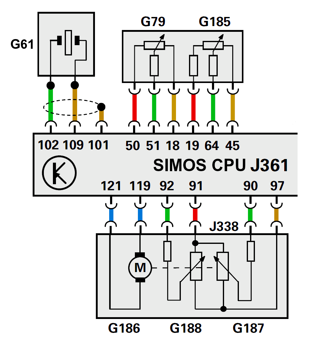 |
| Siemens Simos ECU J361 with pin connections |
Constant movement of the gold plated contacts on the potentiometer slider eventually wears through and becomes intermittent especially if the vehicle has attained a high millage, considering how may times the accelerator pedal has been stepped-on and released. It can be roughly compared to a volume control that's gone scratchy from constant use, when it finally worked through its carbon track and makes intermittent contact. I've known physical steel throttle cable to last a lot longer than its electronic counter part but they do have a tendency to fray and get stuck inside its sleeve especially when going at high speed, which is kinda dangerous -even life threatening. With the EPC system this will not happen, rather if the "electronic steel threads fray" the microprocessor shuts the system down by switching over to its stored alternative values.
Looking at the diagram for G188 and G187 it can clearly be seen that they share a common 5v supply (pin 91) and a common earth (pin97) with the outputs from pins 90 and 92 acting as inputs to the ECU microprocessor that control for the throttle valve actuator motor. These inputs are also constantly monitored by the ECU main Processor and its companion watchdog processor. Noting once again that G188 and G187 act as angle sensors much like that of the accelerator position senders. The concept and principal is exactly the same as that for the accelerator potentiometers. When any discrepancy is detected, a shutdown path is enabled which presents itself to the motorist as a car that won't rev. Then there is G61, the knock sensor. Any knock higher or vibration outside of that expected by the ECU on pin 102 will also enable a shutdown path and sequence limp mode.
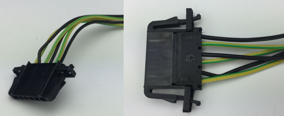 |
| Accelerator 6 pin plug and harness for VW, Golf, Skoda, Fabia, Audi etc. |
| Accelerator Pedal 6 Pin Plug Connector Wiring Harness for VW, Amarok, Beetle, Eos, Lupo, Polo,Touareg, Sharan, Transporter, Electronic - 3B0 972 706 |
No comments:
Post a Comment
Thank you for visiting....